| Part Number: | ULO | - | DB442 | - | 09 | B | N | 0 | P | A | 1 | A | 1 |
|---|---|---|---|---|---|---|---|---|---|---|---|---|---|
| Explanation: |
Brand ULO - ULO |
Model DB442 - D-sub ribbon cable assembly |
Contacts 09 - 9 contacts |
Housing Colour B - Black |
Shell Plating N - Nickel |
Contact Plating 0 - Selective gold flash |
Rivet P - Threaded UNC #4-40 |
Cable Colour A - Grey flat cable |
Diameter / Marking 1 - Ø0.100mm; flower mark |
Length L A - 150mm |
Cable Style 1 - Type 1 |
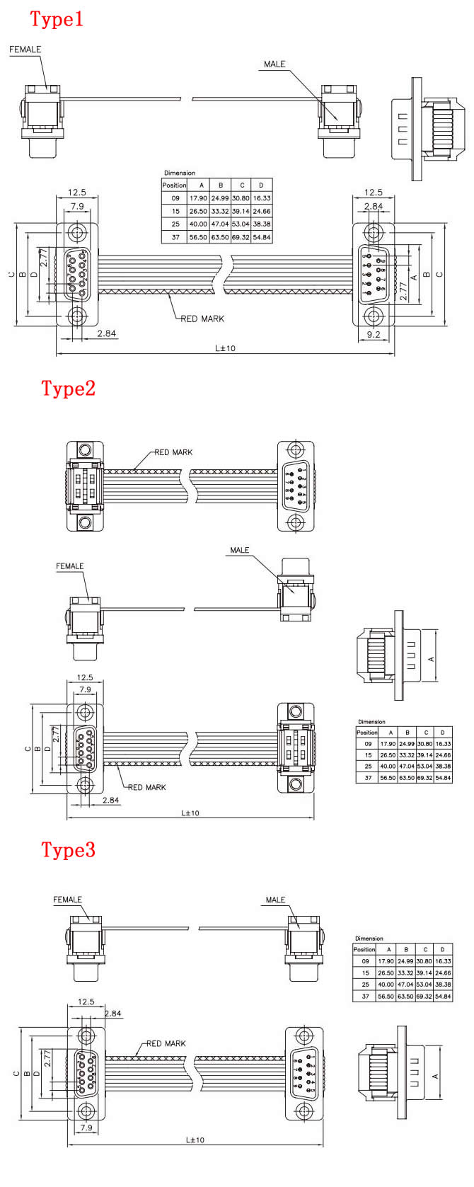
ULO-DB442 pairs male and female D-sub connectors on grey flat cable. Select 9, 15, 25 or 37 contacts, Type 1, Type 2 or Type 3 connector orientation, and the required length and marking option. The three assembly drawings distinguish connector orientation and cable-mark position. Internal pin mapping and protocol compatibility are unspecified.
| Characteristic | DB442 |
|---|---|
| Insulation resistance | ≥1000MΩ |
| Contact impedance | ≤20mΩ |
| Dielectric withstand test | 500VAC for 1 minute |
| Operating temperature | 0°C to +70°C |
| Storage temperature | -20°C to +70°C |
| Insulation material | Thermoplastic, material group I |
| Material flammability grade | UL94V-0 |
| Contact material | Copper alloy |
| Shell material | Steel |
Current rating and working voltage are unspecified. The 500VAC value is a one-minute dielectric withstand test.
| Field | Code | Option |
|---|---|---|
| Connector positions | 09 / 15 / 25 / 37 | 9 / 15 / 25 / 37 contacts |
| Insulator colour | B / L | Black / blue |
| Shell plating | N | Nickel |
| Contact plating | 0 | Selective gold flash |
| Rivet type | P / N | Threaded UNC #4-40 / unthreaded |
| Flat cable colour | A | Grey |
| Cable style | 1 / 2 / 3 | Type 1 / Type 2 / Type 3 |
| Code | Wire-diameter option | Marking |
|---|---|---|
| 1 | Ø0.100mm | Flower mark |
| 2 | Ø0.127mm | Red mark |
| 3 | Ø0.100mm | Red mark |
| 4 | Ø0.127mm | Flower mark |
The wire-diameter field does not specify strand count or total conductor cross-section.
| Length code | Nominal L | Drawing tolerance |
|---|---|---|
| A | 150mm | ±10mm |
| B | 500mm | ±10mm |
| C | 100mm | ±10mm |
| D | 400mm | ±10mm |
| E | 1500mm | ±10mm |
| F | 1525mm | ±10mm |

The following mating dimensions apply to the three illustrated cable styles. Values are in millimetres: A is male mating width, B mounting centres, C flange length and D female mating width.
| Contacts | A | B | C | D |
|---|---|---|---|---|
| 9 | 17.90 | 24.99 | 30.80 | 16.33 |
| 15 | 26.50 | 33.32 | 39.14 | 24.66 |
| 25 | 40.00 | 47.04 | 53.04 | 38.38 |
| 37 | 56.50 | 63.50 | 69.32 | 54.84 |
The illustrated connectors use 2.77mm contact pitch and 2.84mm row spacing. Flange-height reference is 12.5mm, with 7.9mm female and 9.2mm male mating-height references. Select the exact Type 1, Type 2 or Type 3 drawing for the connector orientation, red-mark position and L measurement endpoints.