


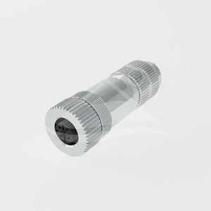

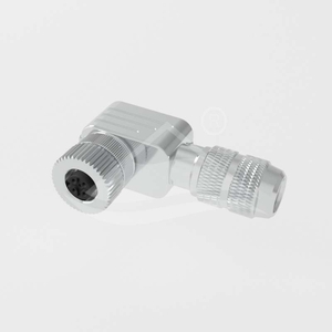
| Part Number: | ULO | - | CC03 | - | M12 | A | - | 04P | - | MM | - | PB | SH | - | SL | 001 |
|---|---|---|---|---|---|---|---|---|---|---|---|---|---|---|---|---|
| Explanation: |
Manufacturer ULO - ULO connector identifier |
Series CC03 - Circular connector family; this breakdown covers the eight listed M12 field-wireable body families and their documented drawing options. |
Interface M12 - M12 circular mating interface |
Coding A - A-coded, 3, 4, 5, 6 or 8 contacts |
Contact Count Code 03P - 3 contacts, A-coded |
Contact Gender MM - Male contacts |
Termination Code PA - Field assembly, solder termination |
Shielding Blank - Omit this field; unshielded body |
Body Code SL - Straight body |
Cable Entry 001 - Cable diameter 4.5–6.0mm |
These M12 field-wireable connectors are available in eight body configurations. Select the contact gender, cable exit direction and shielding before specifying the coding, pin count and termination. Matching thread size alone does not establish electrical or mechanical interchangeability.
| Model family | Contacts | Body | Shielding |
|---|---|---|---|
| ULO-CC03-M12X-XXP-MM-PX-SL00X | Male | Straight | Unshielded |
| ULO-CC03-M12X-XXP-FF-PX-SL00X | Female | Straight | Unshielded |
| ULO-CC03-M12X-XXP-MM-PX-SR00X | Male | Angled | Unshielded |
| ULO-CC03-M12X-XXP-FF-PX-SR00X | Female | Angled | Unshielded |
| ULO-CC03-M12X-XXP-MM-PXSH-SL00X | Male | Straight | Shielded |
| ULO-CC03-M12X-XXP-FF-PXSH-SL00X | Female | Straight | Shielded |
| ULO-CC03-M12X-XXP-MM-PXSH-SR00X | Male | Angled | Shielded |
| ULO-CC03-M12X-XXP-FF-PXSH-SR00X | Female | Angled | Shielded |
The following coding and contact-count combinations are listed for the eight model families. Use the matching connector-face drawing when selecting the mating interface.
| Coding | Contacts | Rated current | Rated voltage | Withstand voltage |
|---|---|---|---|---|
| A | 3 or 4 | 4A | 250V | 1500VAC |
| A | 5 | 4A | 60V | 1200VAC |
| A | 6 or 8 | 2A | 30V | 650V |
| B | 5 | 4A | 60V | 1120V |
| D | 4 | 4A | 250V | 1500V |
Withstand test duration is not specified. AC test notation is given for the A-coded 3-, 4- and 5-contact versions; the other withstand values do not specify the waveform.
| Termination option code | Construction |
|---|---|
| A | Field assembly, solder termination |
| S | Field assembly with plastic nut, solder termination |
| B | Field assembly, screw termination |
| W | Field assembly with plastic nut, screw termination |
| Cable entry code | Cable diameter |
|---|---|
| 001 | 4.5-6.0mm |
| 002 | 6.0-7.5mm |
| 003 | 6.5-10.0mm |
Use the option codes with the individual model drawing. The family identifiers contain placeholders and are not complete order codes; select only the documented coding and contact-count combinations.
| Characteristic | Specification |
|---|---|
| Mating thread | M12×1.0 |
| Contact resistance | ≤3mΩ |
| Protection rating | IP67 |
| Operating temperature | -40°C to +85°C |
| Mechanical mating life | >50 insertion and withdrawal cycles |
| Contact material | CuZn copper-zinc alloy |
| Contact surface | Gold |
| Contact carrier | PA polyamide |
| Sealing material | Silicone |
| Metal ring material, shielded versions | Nickel-plated copper alloy |
| Flammability classification | UL94V-0 |
| Compliance | RoHS |
| Configuration | Drawing dimensions |
|---|---|
| Male straight, MM-PX-SL00X | 62.40mm length; Ø20mm |
| Female straight, FF-PX-SL00X | 51.5mm reference length; Ø20mm |
| Male angled, MM-PX-SR00X | 40mm × 36mm reference envelope; Ø20mm |
| Female angled, FF-PX-SR00X | 38mm × 36mm reference envelope; Ø20mm |


| Configuration | Drawing dimensions |
|---|---|
| Male straight, MM-PXSH-SL00X | 62mm reference length; Ø20mm |
| Female straight, FF-PXSH-SL00X | 56mm reference length; Ø20mm |
| Male angled, MM-PXSH-SR00X | 41.8mm × 54mm reference envelope; Ø20mm |
| Female angled, FF-PXSH-SR00X | 37mm × 54mm reference envelope; Ø20mm |


| General drawing tolerance | Value |
|---|---|
| One decimal place, .X | ±0.3mm |
| Two decimal places, .XX | ±0.1mm |
| Angles | ±1° |
Dimensions marked as reference values retain that designation. Consult the corresponding PDF for connector-face pin numbering and the complete model drawing.
