


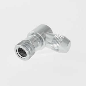
| Part Number: | ULO | - | CC02 | - | M8 | A | - | 04P | - | MM | - | PB | SH | - | SL001 |
|---|---|---|---|---|---|---|---|---|---|---|---|---|---|---|---|
| Explanation: |
Manufacturer ULO - ULO connector identifier |
Series CC02 - Circular connector family; this breakdown covers the eight listed M8 field-wireable body families and their documented drawing options. |
Interface M8 - M8 circular mating interface |
Coding A - A-coded, 3, 4, 6 or 8 contacts |
Contact Count Code 03P - 3 contacts, A-coded |
Contact Gender MM - Male contacts |
Termination Code PA - Field assembly, solder termination |
Shielding Blank - Omit this field; unshielded body |
Body Code SL001 - Straight field-wireable body |
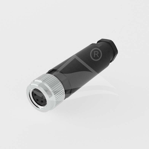
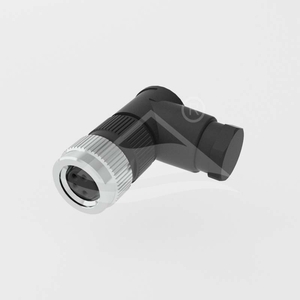
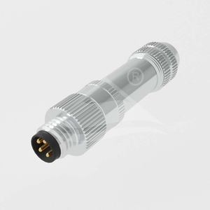
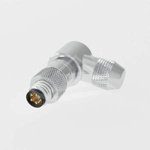
Eight field-wireable connector families cover male and female contacts, straight and angled cable exits, and shielded or unshielded construction. Each uses an M8×1.0 mating thread. Choose the coding and contact arrangement to match the mating device.
| Model family | Contacts | Body | Shielding |
|---|---|---|---|
| ULO-CC02-M8X-XXP-MM-PX-SL001 | Male | Straight | Unshielded |
| ULO-CC02-M8X-XXP-FF-PX-SL001 | Female | Straight | Unshielded |
| ULO-CC02-M8X-XXP-MM-PX-SR001 | Male | Angled | Unshielded |
| ULO-CC02-M8X-XXP-FF-PX-SR001 | Female | Angled | Unshielded |
| ULO-CC02-M8X-XXP-MM-PXSH-SL001 | Male | Straight | Shielded |
| ULO-CC02-M8X-XXP-FF-PXSH-SL001 | Female | Straight | Shielded |
| ULO-CC02-M8X-XXP-MM-PXSH-SR001 | Male | Angled | Shielded |
| ULO-CC02-M8X-XXP-FF-PXSH-SR001 | Female | Angled | Shielded |
| Coding | Contact count | Rated current | Rated voltage | Withstand voltage |
|---|---|---|---|---|
| A | 3 or 4 | 3A | 60VDC | 850V |
| B | 5 | 3A | 30V | 650V |
| A | 6 or 8 | 1.5A | 30V | 650V |
Withstand waveform and test duration are not specified. The five-contact drawing uses B coding; the three-, four-, six- and eight-contact drawings use A coding. Match the individual face drawing and contact numbers rather than selecting by thread size alone.
| Option code | Termination |
|---|---|
| A | Field assembly with solder termination |
| S | Plastic-nut field assembly with solder termination |
| B | Field assembly with screw termination |
| W | Plastic-nut field assembly with screw termination |
The family codes include placeholders for coding, contact count and termination. Use the selected model's PDF to specify the required configuration.
| Characteristic | Specification |
|---|---|
| Contact resistance | ≤3mΩ |
| Protection rating | IP67 |
| Operating temperature | -40°C to +85°C |
| Mating life | ≥100 insertion and withdrawal cycles |
| Contact material | CuZn copper-zinc alloy |
| Contact surface | Gold |
| Contact carrier | PA polyamide |
| Seal | Silicone |
| Metal ring, shielded versions | Nickel-plated copper alloy |
| Flammability classification | UL94V-0 |
| Compliance | RoHS |
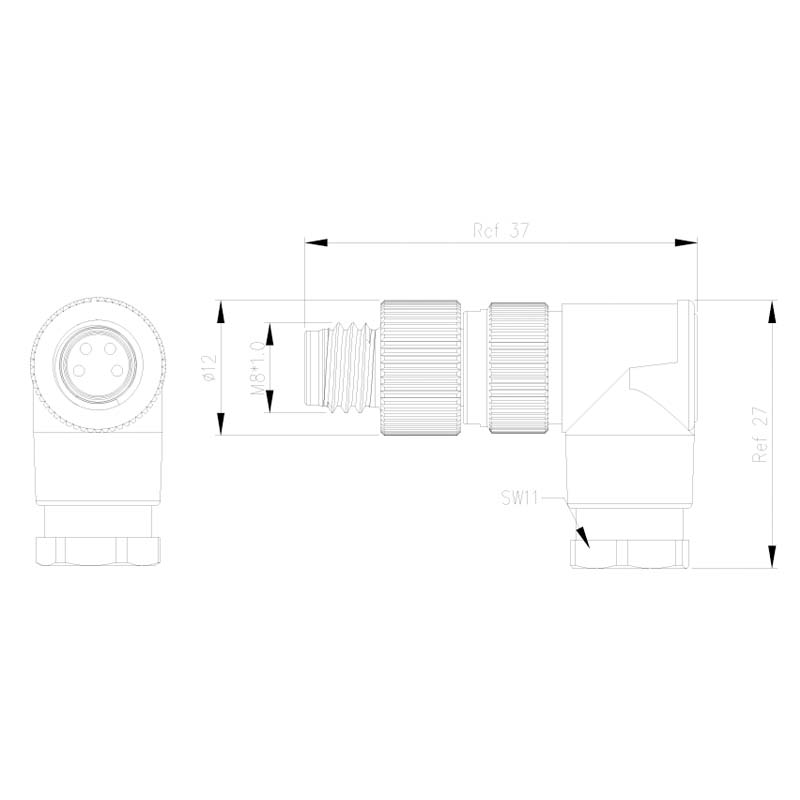
| Configuration | Reference dimensions | Other drawing dimensions |
|---|---|---|
| Straight male, MM-PX-SL001 | 49mm length | Ø12mm; SW11 |
| Straight female, FF-PX-SL001 | 44mm length | Ø12mm; SW11 |
| Angled male, MM-PX-SR001 | 37mm × 27mm | Ø12mm; SW11 |
| Angled female, FF-PX-SR001 | 31mm × 24mm | Ø12mm; SW11 |



| Configuration | Drawing dimensions |
|---|---|
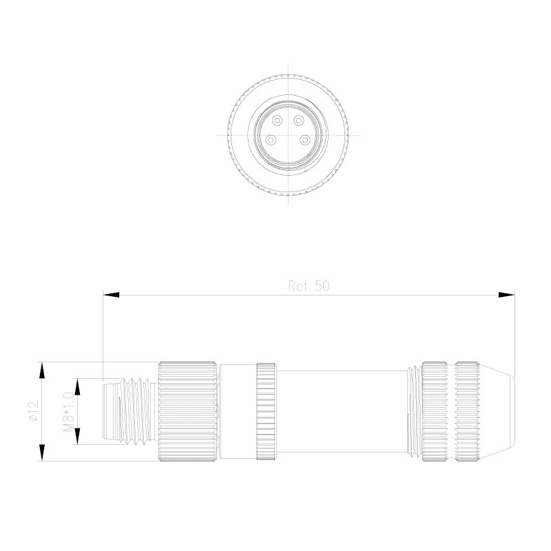
| Straight male, MM-PXSH-SL001 | 50mm reference length; Ø12mm |
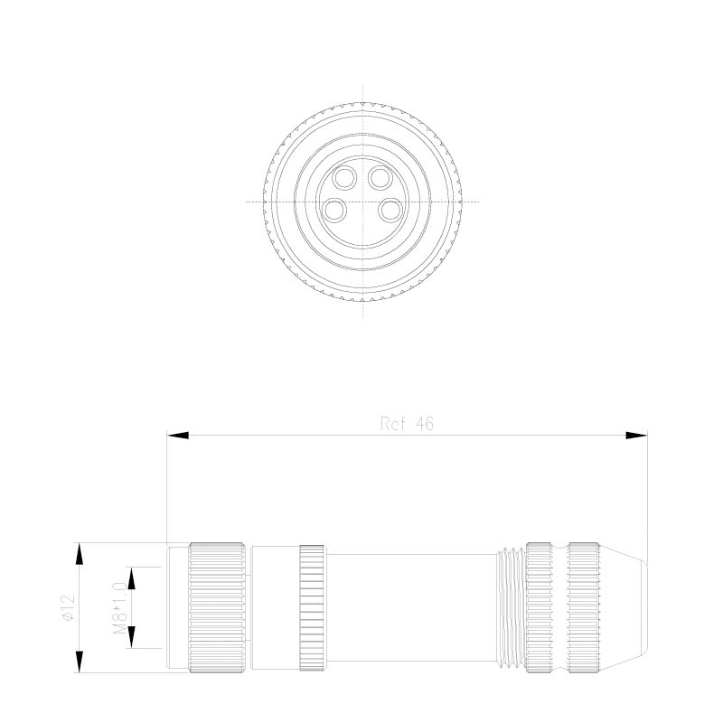
| Straight female, FF-PXSH-SL001 | 46mm reference length; Ø12mm |
| Angled male, MM-PXSH-SR001 | 38.45mm length; 30mm reference height; 23mm reference centreline-to-cable-entry distance; Ø12mm |
| Angled female, FF-PXSH-SR001 | 30mm reference length and height; 23mm reference centreline-to-cable-entry distance; Ø12mm |


| General drawing tolerance | Value |
|---|---|
| One decimal place, .X | ±0.3mm |
| Two decimal places, .XX | ±0.1mm |
| Angles | ±1° |
Reference dimensions retain their reference designation. The corresponding PDFs include the contact-face drawings and model option legends.
