| Part Number: | ULO | - | PCB454 | - | 2 | M | R | W | 6 | X | A |
|---|---|---|---|---|---|---|---|---|---|---|---|
| Explanation: |
Brand ULO - ULO |
Family PCB454 - 2.0mm PH connector family; order required components separately |
Contacts 2–15 - Number of contacts |
Connector Type F - Female |
Mounting / Termination V - Vertical male PCB header |
Colour W - White |
Plating 6 - Tin |
Contact Form X - Without kink |
Right-angle Bend A - Type A; right-angle header only |
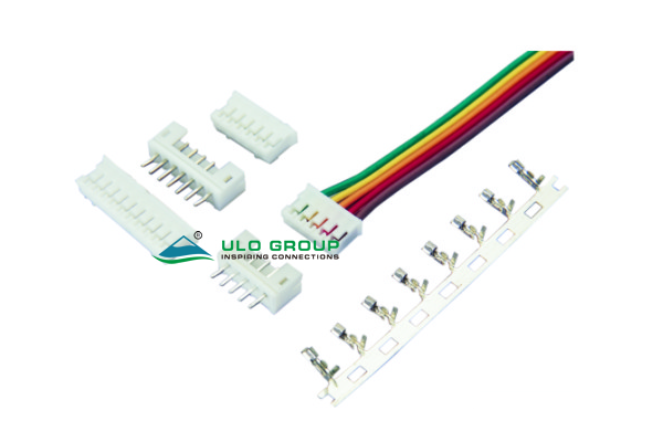
ULO-PCB454 combines a female cable housing, female crimp terminals and a male PCB header at 2.0mm pitch. Select these components separately for the cable and board assembly. The range covers 2 to 15 positions; male headers are available in vertical and right-angle forms.
| Component | Selection | Ordering scope |
|---|---|---|
| Female housing | 2–15 positions; 2.0mm pitch | Select position count and housing colour |
| Female terminal | Crimp termination for 30–24AWG wire | Select terminals separately from the housing |
| Male PCB header | 2–15 positions; vertical or right-angle | Select position count, orientation, plating and contact form |
The family designation is PCB454. Separate suffix part numbers for the loose housing and terminal are unspecified. Define the required component quantities in the order; a complete cable-and-header set is not implied.
| Characteristic | PCB454 |
|---|---|
| Rated current | 1A |
| Rated voltage | 250V |
| Contact impedance | ≤30mΩ |
| Insulation impedance | ≥1000MΩ |
| Dielectric withstand test | 500VAC for 1 minute |
| Operating temperature | -25°C to +85°C |
| Storage temperature | -25°C to +85°C |
| Board thickness reference | 1.6mm |
| Insulator | Nylon 66, material group I |
| Material flammability grade | UL94V-0 |
| Contact material | Copper alloy |
| Ordering field | Code and meaning |
|---|---|
| Contact count | 2–15 |
| Connector type | F: female; M: male |
| Termination or mounting | V: vertical; C: crimp; R: right-angle |
| Housing colour | W: white; T: transparent |
| Contact plating | 6: tin; 8: full gold flash |
| Contact form | X: without kink; S: with kink |
| Right-angle bend | A: type A; B: type B |
The bend field applies to right-angle headers. Crimp termination belongs to the female terminal, while the vertical and right-angle profiles describe male PCB headers. Use the component drawings to select applicable fields.

| Conductor area | Wire gauge | Wire outside diameter |
|---|---|---|
| 0.05–0.22mm² | 30–24AWG | 0.9–1.5mm |
The female terminal outline shows 5.70mm overall length, with 2.85mm, 2.05mm and 1.50mm longitudinal references. Its end view includes 1.0mm and 2.08mm references. Use both conductor area and insulation outside diameter when selecting wire.
Dimension A is the first-to-last contact span. B is the body length and differs by 0.1mm between the female housing and male header at the same position count. Values in the following table are in millimetres.
| Positions | Female A | Female B | Male A | Male B |
|---|---|---|---|---|
| 2 | 2.0 | 5.8 | 2.0 | 5.9 |
| 3 | 4.0 | 7.8 | 4.0 | 7.9 |
| 4 | 6.0 | 9.8 | 6.0 | 9.9 |
| 5 | 8.0 | 11.8 | 8.0 | 11.9 |
| 6 | 10.0 | 13.8 | 10.0 | 13.9 |
| 7 | 12.0 | 15.8 | 12.0 | 15.9 |
| 8 | 14.0 | 17.8 | 14.0 | 17.9 |
| 9 | 16.0 | 19.8 | 16.0 | 19.9 |
| 10 | 18.0 | 21.8 | 18.0 | 21.9 |
| 11 | 20.0 | 23.8 | 20.0 | 23.9 |
| 12 | 22.0 | 25.8 | 22.0 | 25.9 |
| 13 | 24.0 | 27.8 | 24.0 | 27.9 |
| 14 | 26.0 | 29.8 | 26.0 | 29.9 |
| 15 | 28.0 | 31.8 | 28.0 | 31.9 |
| Component reference | Dimension or form |
|---|---|
| Female housing | 4.50mm side width; 6.35mm height reference; 0.50mm upper detail |
| Male header housing | 4.80mm side width; 6.00mm body height; 1.70mm internal reference |
| Male contact-width reference | 0.50mm |
| Vertical header tail | 3.4mm projection; with or without kink |
| Right-angle type A | 3.4mm horizontal tail projection; 1.60mm lower reference; 6.25mm profile reference |
| Right-angle type B | 3.4mm horizontal tail projection; 6.25mm profile reference |

