
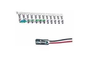
The TJC8 family includes two distinct pitches: ULO-PCB459 uses 2.54mm, while ULO-PCB459A uses 2.0mm. Select the exact model and row arrangement before choosing a housing or terminal.
| Model | Pitch | Female housing ordering range | Component coverage |
|---|---|---|---|
| ULO-PCB459 | 2.54mm | Single row: 1 × 1 to 1 × 40; dual row: 2 × 2 to 2 × 40 | Female crimp housing and terminal; male vertical and right-angle header outlines also shown |
| ULO-PCB459A | 2.0mm | Single row: 1 × 1 to 1 × 40; dual row: 2 × 1 to 2 × 40 | Female crimp housing and terminal; dual-row housing outline shown |
In row notation, the first number is the number of rows and the second is the contacts per row. Specify housing and terminal quantities separately. The PCB459 male header drawings provide dimensional references; corresponding male ordering suffixes are unspecified. Cable lengths and assembled cable quantities are unspecified.
| Characteristic | PCB459 and PCB459A |
|---|---|
| Rated current | 1A |
| Rated voltage | 250V |
| Contact impedance | ≤30mΩ |
| Insulation impedance | ≥1000MΩ |
| Dielectric withstand test | 500VAC for 1 minute |
| Operating temperature | -25°C to +85°C |
| Storage temperature | -25°C to +85°C |
| Thickness reference | 1.6mm |
| Insulator | Nylon 66, material group I |
| Material flammability grade | UL94V-0 |
| Contact material | Copper alloy |
| Model | Wire gauge | Conductor area | Wire outside diameter | Terminal overall length |
|---|---|---|---|---|
| PCB459 female terminal | 28–22AWG | 0.05–0.3mm² | 1.7mm | 11.50mm |
| PCB459A terminal | 24–18AWG | Unspecified | Unspecified | 10.00mm |
Apply wire data to the exact model. Crimp tooling and stripping settings are unspecified.
| Field | PCB459 | PCB459A |
|---|---|---|
| Row and contact selection | 1 × 1–40 or 2 × 2–40 | 1 × 1–40 or 2 × 1–40 |
| Connector type | F: female | F: female |
| Termination | C: crimp | C: crimp |
| Housing colour | B: black | B: black |
| Contact plating | 6: tin; 8: full gold flash | 6: full tin; 8: full gold flash |


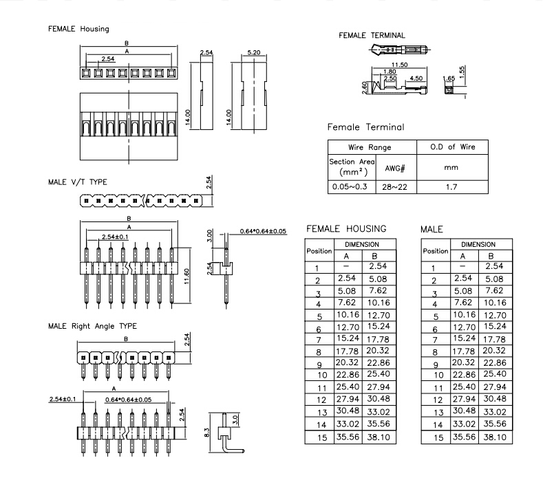
The following A/B values apply to the single-row female housing and male header outlines shown. All values are in millimetres. The available dimension table covers positions 1 to 15; the ordering range extends further.
| Positions | Female housing | Male header | ||
|---|---|---|---|---|
| A | B | A | B | |
| 1 | — | 2.54 | — | 2.54 |
| 2 | 2.54 | 5.08 | 2.54 | 5.08 |
| 3 | 5.08 | 7.62 | 5.08 | 7.62 |
| 4 | 7.62 | 10.16 | 7.62 | 10.16 |
| 5 | 10.16 | 12.70 | 10.16 | 12.70 |
| 6 | 12.70 | 15.24 | 12.70 | 15.24 |
| 7 | 15.24 | 17.78 | 15.24 | 17.78 |
| 8 | 17.78 | 20.32 | 17.78 | 20.32 |
| 9 | 20.32 | 22.86 | 20.32 | 22.86 |
| 10 | 22.86 | 25.40 | 22.86 | 25.40 |
| 11 | 25.40 | 27.94 | 25.40 | 27.94 |
| 12 | 27.94 | 30.48 | 27.94 | 30.48 |
| 13 | 30.48 | 33.02 | 30.48 | 33.02 |
| 14 | 33.02 | 35.56 | 33.02 | 35.56 |
| 15 | 35.56 | 38.10 | 35.56 | 38.10 |
The female housing is 14.00mm high; side profiles show 2.54mm and 5.20mm widths. Male header contacts are 0.64 × 0.64mm with a ±0.05mm reference tolerance. Header base height is 2.54mm, the vertical header shows 11.60mm overall length and a 3.00mm end reference, and the right-angle header shows an 8.3mm reference and 3.10mm bent-tail reference. Header pitch is 2.54±0.1mm.
The dual-row housing drawing uses 2.00mm contact and row pitch, a 4.10mm width and a 7.23mm height. With N contacts per row, the contact span is (N − 1) × 2.00mm and the housing row length is N × 2.00mm + 0.36mm. The terminal has a 10.00mm overall length, 6.34mm, 3.50mm and 1.00mm longitudinal references, a 1.34mm tip-width reference and 1.92mm/1.60mm crimp-section widths.

