
| Part Number: | ULO | - | PJ515 | - | S | 8 | 0 | B | P |
|---|---|---|---|---|---|---|---|---|---|
| Explanation: |
Brand ULO - ULO |
Model PJ515 - Shielded 10-position socket |
Connector Type S - Socket |
Contacts 6 - 10P6C; PJ515 only |
Plating 0 - Gold flash |
Colour B - Black |
Material P - PBT |
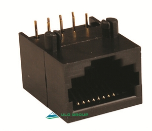
ULO-PJ515 and ULO-PJ523 are single-port modular sockets for through-hole PCB mounting. P identifies the number of housing positions and C the number of populated contacts. Select the contact population and exact model together.
| Model | Housing positions | Contact population | Contact-count code | Construction |
|---|---|---|---|---|
| ULO-PJ515 | 10 | 10P4C: 4 contacts | Unspecified | Metal-shielded socket |
| ULO-PJ515 | 10 | 10P6C: 6 contacts | 6 | Metal-shielded socket |
| ULO-PJ515 | 10 | 10P8C: 8 contacts | 8 | Metal-shielded socket |
| ULO-PJ515 | 10 | 10P10C: 10 contacts | 10 | Metal-shielded socket |
| ULO-PJ523 | 10 | 10P8C: 8 contacts | 8 | Unshielded socket |
| ULO-PJ523 | 10 | 10P10C: 10 contacts | 10 | Unshielded socket |
| Characteristic | Value | Applicability |
|---|---|---|
| Insulation resistance | ≥1000MΩ | Both models |
| Dielectric withstand test | 500VAC for 1 minute | Both models |
| Mating life | ≥600 cycles | Both models |
| Insulator material | PBT or nylon | Both models |
| Insulation material group | I | Both models |
| Material flammability options | UL94V-0 or UL94V-2 | Both models; grade depends on the selected material option |
| Contact material | Copper alloy | Both models |
| Shield material | Copper alloy | PJ515 |
Current rating, working voltage, operating temperature and ingress-protection rating are unspecified. The dielectric withstand value is a test condition.
| Field | Code | Option | Models |
|---|---|---|---|
| Connector type | S | Socket | Both |
| Insulator material | P / N | PBT / nylon | Both |
| Insulator colour | B | Black | Both |
| Contact finish | 0 | Gold flash | Both |
| Contact finish | 3 | Selective 3µin gold | Both |
| Additional gold thicknesses | Exact suffix unspecified | 6µin, 15µin or 30µin | Both |
Values are in millimetres. The PCB drawings show all ten potential contact holes; the populated contacts depend on the selected version.
| Reference | PJ515 | PJ523 |
|---|---|---|
| Body width | 16.00 | 15.00±0.15 |
| Body depth | 18.50 | 17.63±0.15 |
| Body height | 13.30 | 12.60±0.15 |
| Contact holes | 10 × Ø0.90 | 10 × Ø0.90 |
| Adjacent stagger reference | 1.27 | 1.27 |
| Contact spacing within a row | 2.54 | 2.54 |
| PCB contact-row spacing | 2.54 | 2.54 |
| Locating-hole centres | 11.43 | 11.43 |
| Locating-hole diameter | 2 × Ø3.25 | 2 × Ø3.20 |
| Contact-row-to-locating-hole reference | 8.89 | 8.89 |
| Shield mounting holes | 2 × Ø1.70; 15.50 span and 3.05 offset | Not applicable |
| Recommended PCB layout tolerance | ±0.05 | ±0.05 |
PJ515 provides a copper-alloy shield and separate shield mounting holes. Its housing drawing also gives an 11.43±0.1mm locating-centre reference and 8.89±0.1mm and 2.54±0.1mm side references. The 10P8C bottom-view diagram identifies eight populated contacts within the ten-position pattern.


PJ523 uses plastic locating posts without an outer metal shield. The contact face shows nine intervals of 1.02mm. Other section references include 15.4mm inner depth, 11mm height, 6.83±0.1mm opening height, Ø0.45mm tails and a 4-4.5mm tail-length reference. The locating-post detail identifies Ø3.0mm, R1.6mm, R0.3mm and the smaller section dimensions used in the moulded retention feature.


