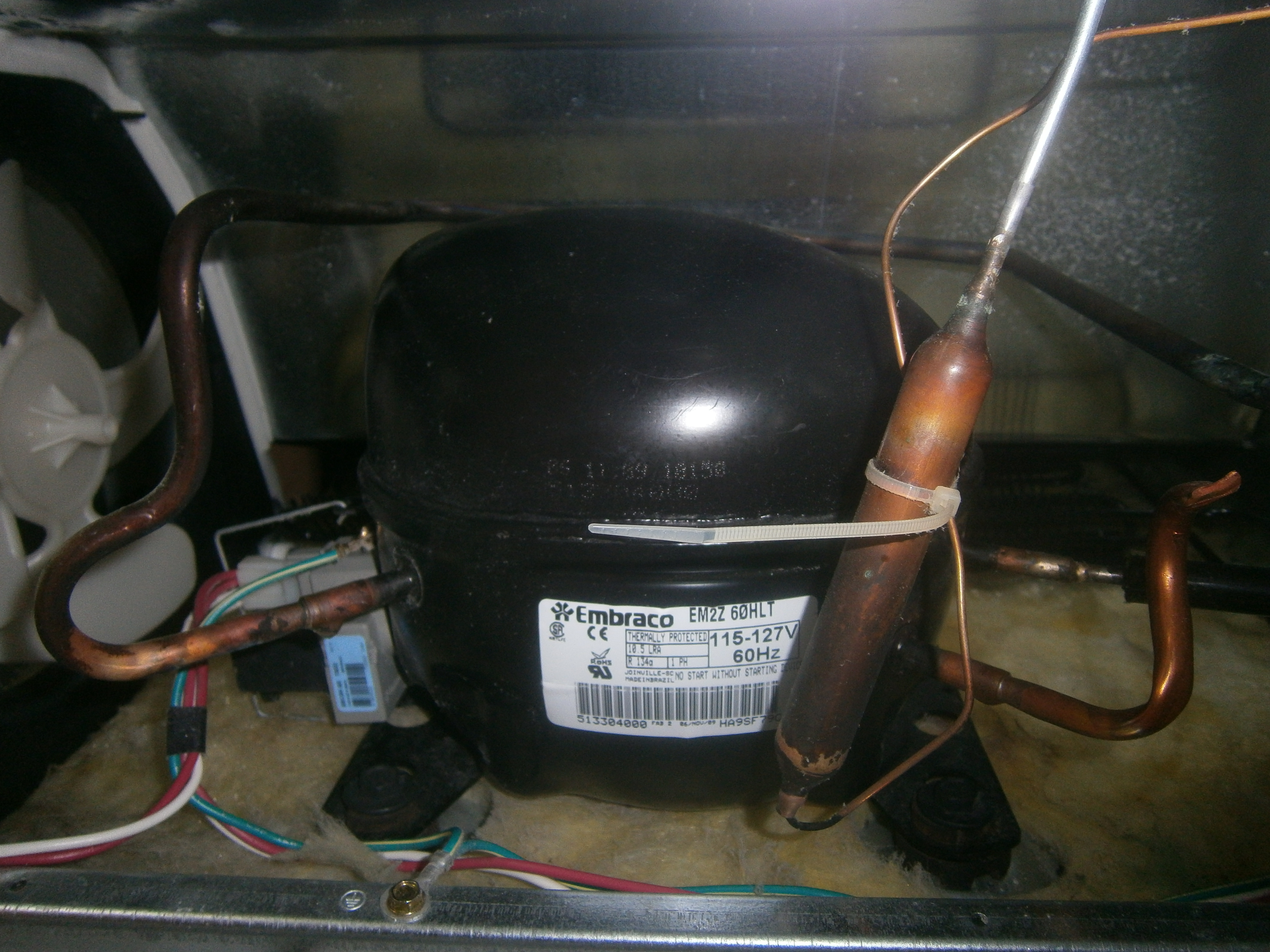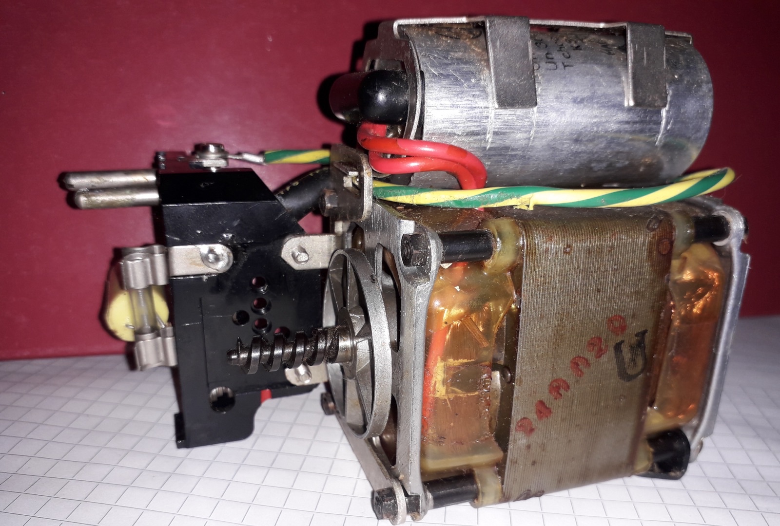
A motor starting capacitor, also called a start capacitor, is an electrical component used briefly during startup in certain single-phase induction motors. It is connected in series with an auxiliary winding and changes the phase of the current through that winding. This helps the motor produce starting torque—the turning force that sets the shaft and its load in motion. Once the motor has accelerated, a switch or starting device removes the capacitor from the circuit.
Start capacitors are used where the motor design calls for strong starting torque, including some compressors and pumps. Their defining feature is this short period of operation. A motor can run for hours while its start capacitor is used only during acceleration, and many single-phase motors use a different starting arrangement altogether.
How a Start Capacitor Produces Starting Torque
A capacitor stores electrical energy in an electric field between conductors separated by an insulating material. In an AC circuit, it repeatedly charges and discharges as the applied voltage changes. That behavior affects when current flows during each electrical cycle. In a motor starting circuit, the useful result is a difference in timing between the currents in two windings.
The main winding of a single-phase induction motor produces a magnetic field that strengthens, weakens, and reverses along a fixed axis. At standstill, this pulsating field alone provides no preferred direction of rotation. Applying power to that winding does not, by itself, give the rotor a dependable start.
A capacitor-start motor also has an auxiliary winding positioned at a different electrical angle around the stator, the stationary part of the motor. The capacitor is connected in series with this winding, so the auxiliary-winding current passes through it. The capacitor changes that current's phase—its timing relative to the main-winding current. Because the two windings are separated in position and their currents are separated in time, their magnetic fields combine to produce starting torque in the intended direction.
This explains what is meant when a start capacitor is said to give a motor a “boost.” The supply provides the energy to accelerate the load; the capacitor helps establish the winding currents that turn that electrical input into starting torque. Its capacitance affects both the current and the phase relationship, so choosing a larger value does not automatically produce a better start.
Why Start Capacitors Must Disconnect After Startup
Getting a stationary load moving and maintaining normal rotation are different operating conditions. A capacitor-start motor uses a circuit chosen for acceleration, then changes that circuit as it approaches running speed. A centrifugal switch may respond directly to shaft speed, while a starting relay uses an electrical signal associated with motor operation. The required switching point is determined by the motor and its starting equipment. The capacitor establishes the auxiliary-winding current; the switch or relay decides when to remove it. The capacitor itself does not sense motor speed or open the starting circuit.
A start capacitor left energized beyond its intended starting duty can overheat. If the motor cannot accelerate, or the starting device fails to remove the capacitor, replacing the damaged capacitor alone may leave the underlying problem unresolved.
Intermittent duty also limits repeated starts. KEMET's MS/MD datasheet gives an example of twenty three-second starts per hour at a 1.67% duty rating; sixty starts per hour reduces the permitted on-time to one second per start. These are conditions for that capacitor specification, not universal motor limits. Both starting duration and recovery time matter, so repeated restart attempts can exceed the capacitor's intended duty.
Start Capacitors vs. Run Capacitors
What remains connected depends on the motor's construction. In a capacitor-start, induction-run motor, the start capacitor and auxiliary winding are disconnected, and the motor continues running with its main winding energized. In a capacitor-start, capacitor-run motor, the start capacitor is removed but the auxiliary winding continues to receive current through a separate run capacitor. The winding's continued operation does not mean that the start capacitor should remain connected.
Motor start capacitors commonly use aluminum-electrolytic construction designed for short AC operation. Inside are wound aluminum foils and separators containing electrolyte, with an aluminum-oxide layer acting as the dielectric—the insulating material that separates the electrical charges. Run capacitors commonly use low-loss film construction suited to continuous energization. These construction and duty differences matter even when two capacitors have similar cases or capacitance values.
There is also a motor arrangement that uses a run capacitor from the beginning: the permanent split capacitor, or PSC, motor. Its capacitor remains connected during both starting and running. This distinction matters because “a capacitor that helps a motor start” is a broader description than “a motor start capacitor.” A PSC motor's continuous-duty capacitor must not be replaced with an intermittent-duty start capacitor. Other designs, such as shaded-pole motors, use a different method and have no motor starting capacitor.
An HVAC dual run capacitor is another source of confusion. It contains two run-capacitor sections in one case, typically serving the compressor and fan motor. For example, a 50 + 7.5 µF unit provides separate 50 µF and 7.5 µF sections; those numbers do not mean “start” and “run.” On common HVAC designs, C identifies the common terminal, HERM the compressor section, and FAN the fan section. A separate start capacitor may still be part of the compressor's starting circuit.
How to Read Capacitance and Voltage Ratings
The capacitor may be housed under a cover on the motor or located with external starting equipment. Its case alone does not establish its function: cylindrical shapes and similar terminals are used on components with different ratings and duties. The label identifies the component, while the equipment wiring diagram establishes its role.
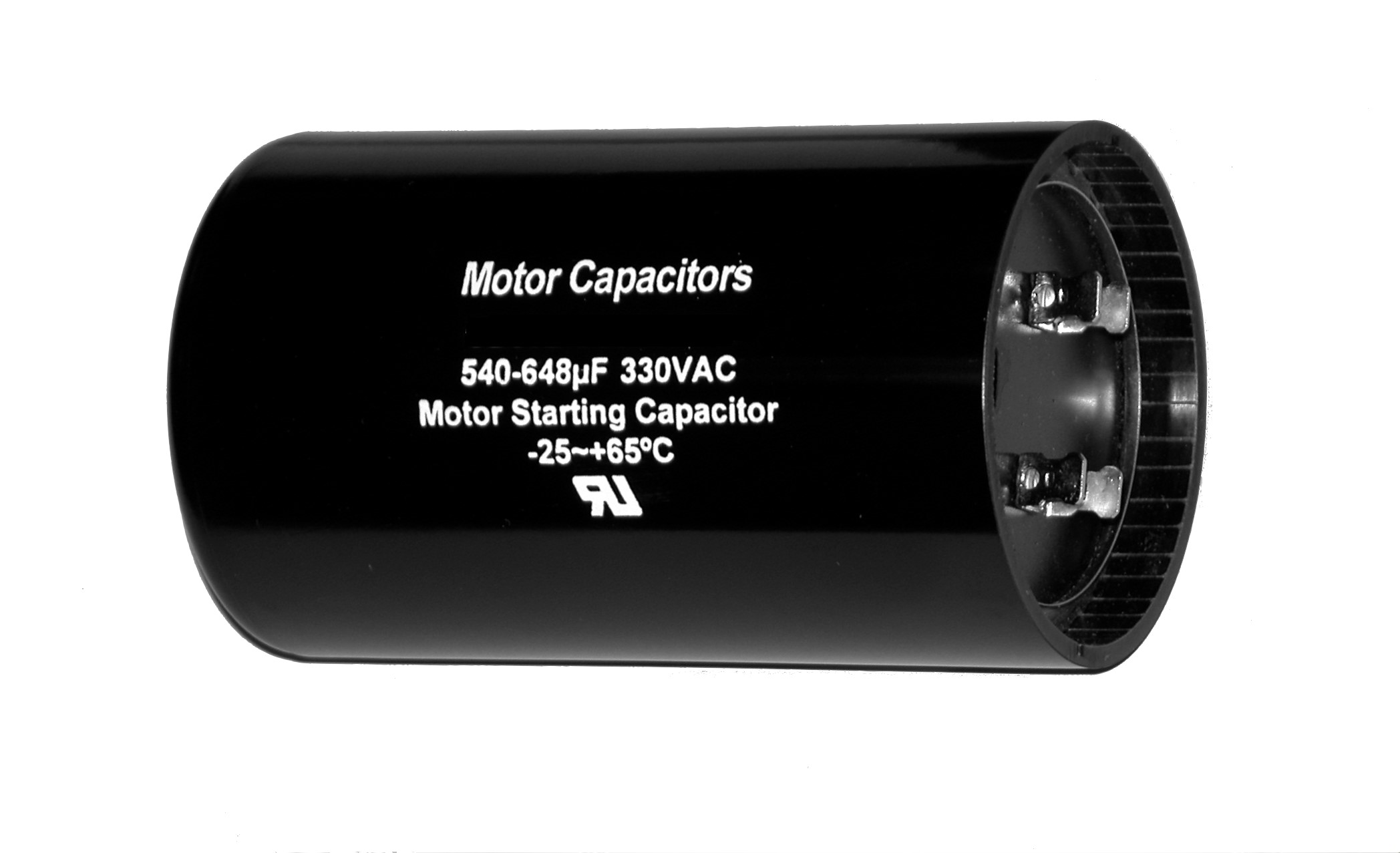
On the capacitor shown here, 540–648 µF is the capacitance range for one capacitor, not two separate capacitances and not an adjustable setting. The unit µF means microfarads; motor-component markings may also use MFD for the same unit. Capacitance determines how the component behaves in the auxiliary-winding circuit. The appropriate value is specified for the motor: excessive starting capacitance can increase winding current and heating and may reduce starting torque.
330 VAC is the capacitor's AC voltage rating. It is not a voltage that the capacitor generates, nor does it identify the motor's supply voltage. The temperature marking is another operating limit. Together with the specified frequency and intermittent duty, these ratings describe the conditions under which the component is intended to work. Matching only one number leaves the other requirements unresolved.
Some start capacitors have a discharge resistor across their terminals. It lets stored charge decay after disconnection and helps limit electrical stress. It is separate from the capacitor's µF rating and does not replace the starting switch. Its presence alone does not establish that the terminals are safe to touch.
For replacement, use the manufacturer's specified part or approved equivalent, including its capacitance range, suitable AC voltage rating, duty, temperature and frequency ratings, terminals, mounting, and any required discharge resistor. An approved higher voltage rating may be acceptable; a lower one is not. If the label is unreadable, the motor or equipment model and its parts documentation are the useful next sources of information.
A motor that hums without turning may have lost the starting torque this circuit should provide, but the capacitor is only one possible cause. A defective starting device, inadequate supply voltage, winding damage, or excessive load can also prevent acceleration. A bulging or leaking capacitor warrants replacement, while a normal-looking case does not establish electrical health. Inspection and measurement require power isolation and verified discharge by someone competent to service mains-powered equipment, because a capacitor can retain charge after power is removed.
A motor starting capacitor is therefore best understood by its place in the motor: it establishes the auxiliary current needed for starting torque during a limited part of the operating cycle. Its capacity to help the motor start and its need to leave the circuit belong to the same design.