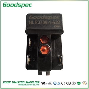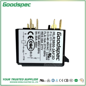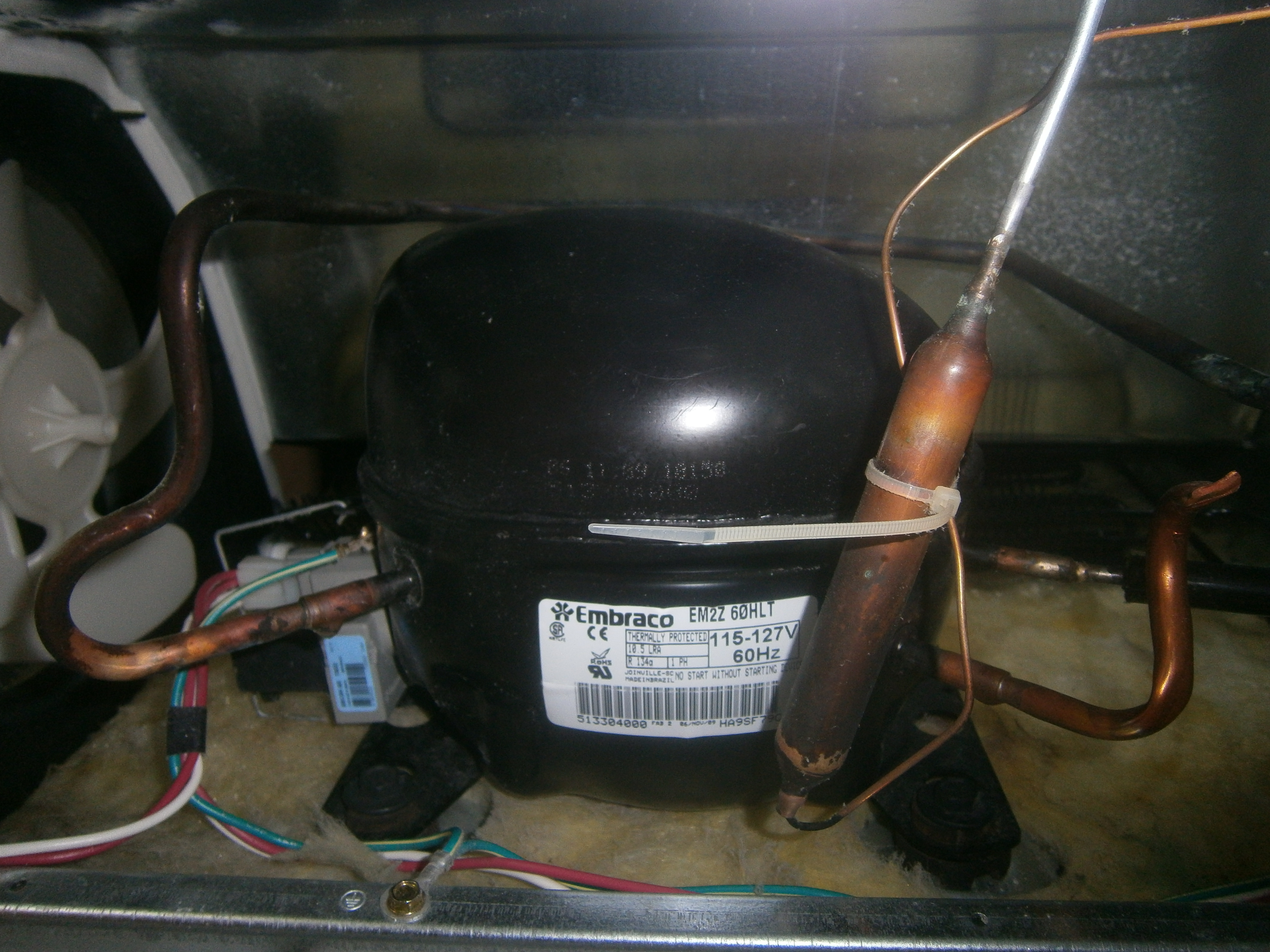
A compressor that hums without starting can have a problem in its starting circuit. One component in that circuit is the motor starting relay: an automatic switching device that controls temporary starting assistance in certain single-phase motors.
Its job is to let the motor develop enough torque to accelerate, then remove the part of the circuit intended only for startup. That does not always mean disconnecting the entire auxiliary winding. Some motors keep that winding energized through a run capacitor. Understanding what the relay switches is the first step toward understanding its operation and selecting a suitable replacement.
Why a Motor Needs a Starting Circuit
Many single-phase induction motors use two windings positioned apart: a main winding and an auxiliary winding. Their currents are made to rise and fall at different times, producing the rotating magnetic effect needed for starting torque. In capacitor-start designs, a capacitor helps create this phase difference. The relay controls the starting connection; the motor and its winding circuit produce the torque.
What happens after acceleration depends on the motor arrangement:
| Motor arrangement | What changes after startup? |
|---|---|
| Resistance-start, induction-run | The auxiliary winding's starting supply is removed. |
| Capacitor-start, induction-run | The start capacitor and auxiliary winding are disconnected from their starting supply. |
| Capacitor-start, capacitor-run | The start capacitor is disconnected; the auxiliary winding remains energized through a run capacitor. |
A permanent split capacitor motor uses a run capacitor continuously and ordinarily needs no separate start-capacitor switching relay. Finding a capacitor beside a motor therefore does not establish that a starting relay must also be present. Other motor designs can use a centrifugal switch, which operates mechanically with shaft speed, to perform the starting-circuit switching function.
The distinction between a start capacitor and a run capacitor matters because their duties differ. A start capacitor is intended for intermittent operation; leaving it connected beyond its intended duty can cause overheating and failure. The equipment's wiring diagram establishes which branch should remain energized during running.
How Current, Potential, and PTC Devices Work
Current Relays
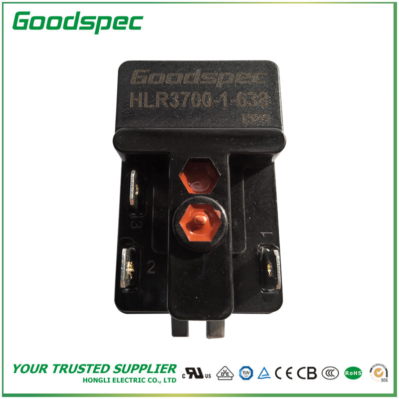
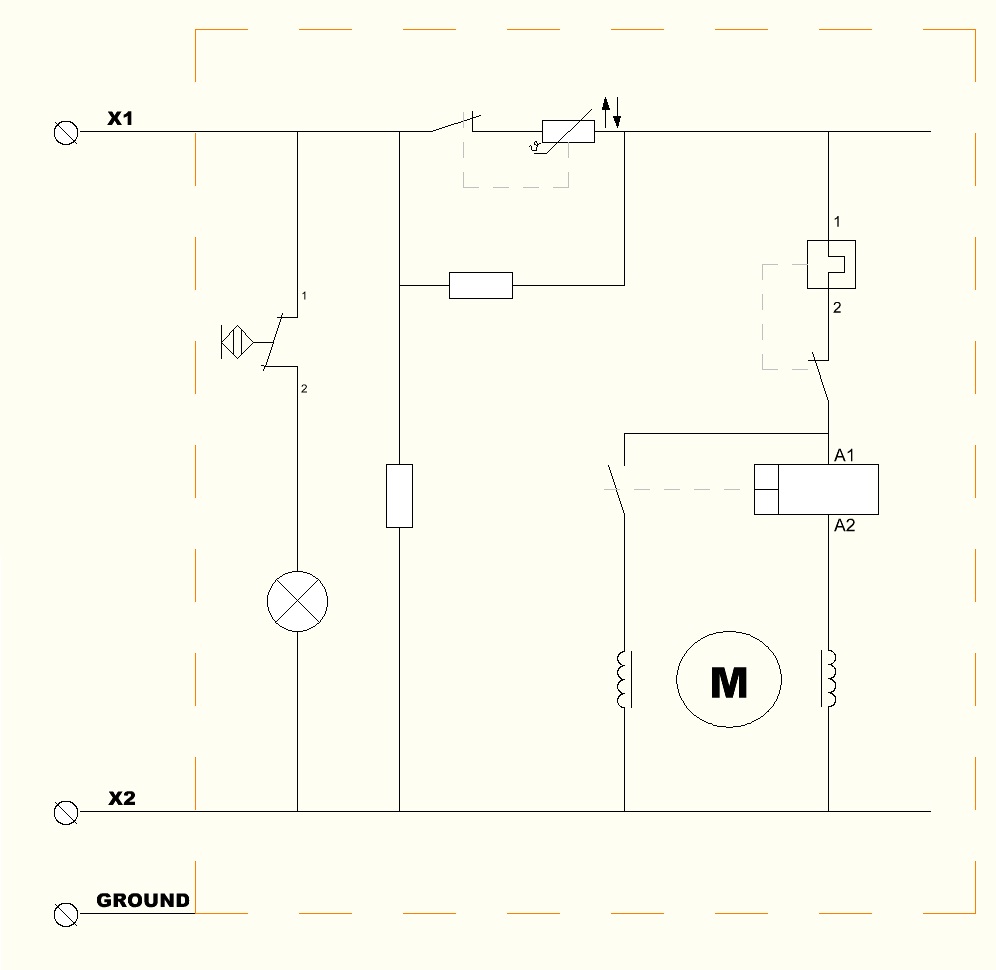
A current relay responds to main-winding current. Its coil is connected in series with the main winding, while its normally open contacts control the starting branch. High current at startup produces enough magnetic force to close the contacts. As the motor accelerates and current falls, the contacts reopen. Pickup and dropout current ratings determine these switching points; they are separate from the contacts' current-carrying rating.
Potential Relays
A potential relay responds to voltage across the auxiliary winding. Its contacts are normally closed, allowing the starting circuit to operate immediately. As the motor accelerates, winding voltage rises. At the pickup threshold, the contacts open to disconnect the start capacitor. The coil remains energized during running and resets when power is removed.
PTC Starters
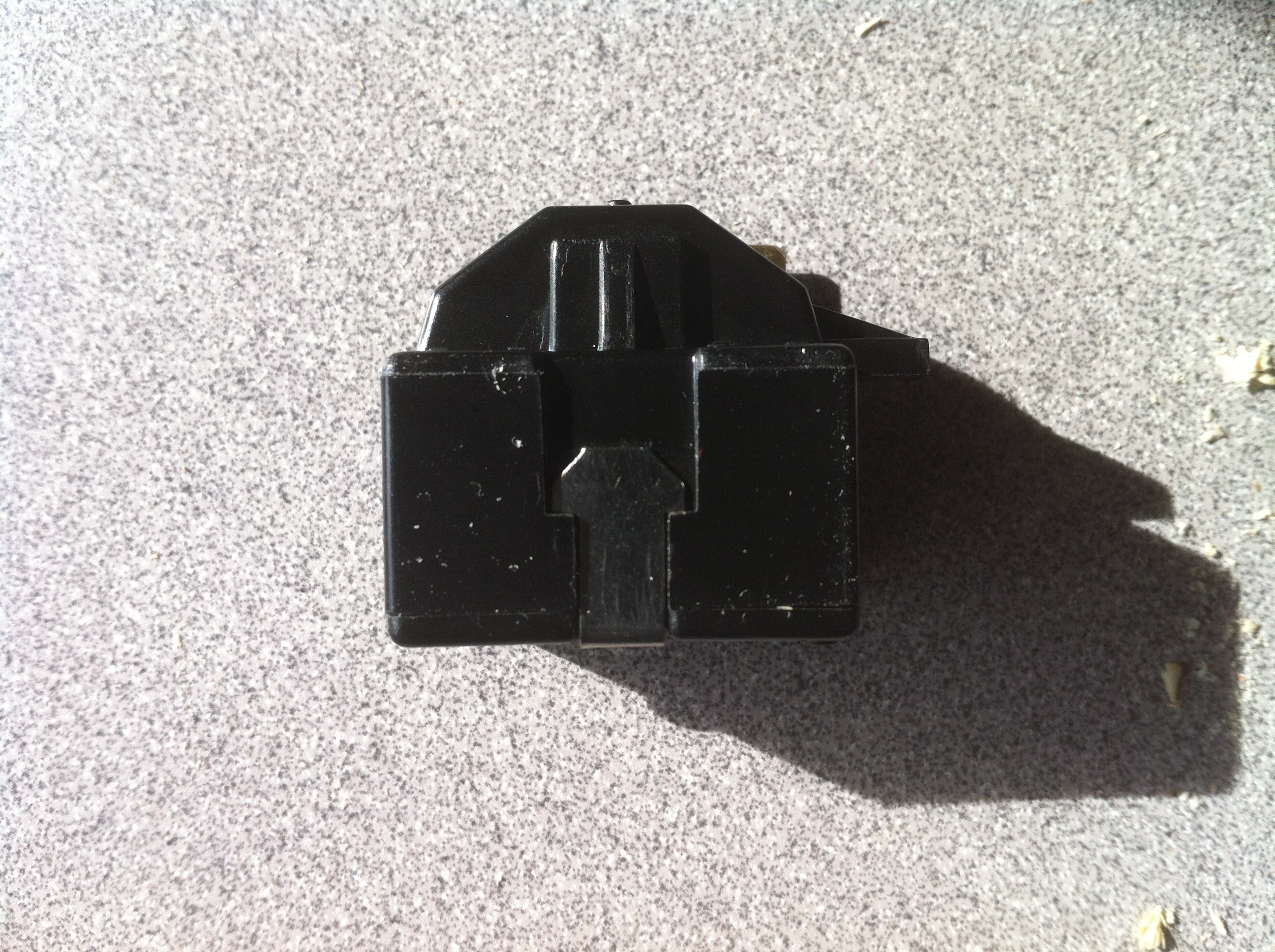
A conventional PTC starter responds to its own temperature. PTC means positive temperature coefficient: resistance increases as the device heats. When cold, its ceramic element permits substantial starting current. That current heats the element, sharply increasing resistance and reducing current through the PTC branch to a small residual value. Although often called a PTC relay, this device has no mechanical switching contacts and does not directly measure motor speed.
Thermal operation affects restarting. A hot PTC can still restrict current when another start is requested. Secop's August 2021 motor-systems bulletin specifies a five-minute cooling period for the conventional PTC arrangements it covers, together with pressure equalization in the relevant refrigeration applications. That interval applies to those arrangements; it is not a universal delay for every starting device. A restart problem that disappears after a pause therefore needs investigation of the required off-time and system conditions before the starter is condemned.
What Determines the Correct Replacement?
Begin with the motor or compressor model and the manufacturer's specified replacement or approved cross-reference. Horsepower, supply voltage, and a matching housing are not enough to establish compatibility. The device must provide the required starting connection and remove it correctly under the equipment's intended operating conditions.
For a current relay, verify pickup and dropout current ratings, contact capacity, terminal arrangement, and mounting requirements. Some designs depend on their installed position; balanced-armature designs such as Sensata's 4CR are designed to operate independently of mounting position. Follow the particular relay's specification rather than applying one mounting rule to every current relay.
For a potential relay, distinguish pickup voltage, dropout voltage, and continuous coil voltage. Pickup initiates contact opening; dropout describes release as coil voltage falls; the continuous rating describes the voltage the coil can withstand continuously. For example, SUPCO's 9068 specifies a 314–342 VAC pickup range, 135 VAC dropout voltage, and 502 VAC continuous coil voltage. These are three different specifications for one relay, not interchangeable descriptions of the motor's supply voltage.
For a PTC starter, use the specified device for the compressor and starting arrangement. Cold resistance affects initial current, while thermal behavior affects how starting assistance decreases and how soon the device can restart. A matching terminal count alone cannot establish those characteristics.
What Starting Symptoms Can Tell You
Humming followed by a thermal-protector trip does not isolate a relay fault. Low voltage, a failed capacitor, incorrect wiring, winding damage, or mechanical trouble can produce similar symptoms. A thermal protector interrupts an abnormal operating condition; it has a different function from switching out the starting branch.
Useful diagnosis starts with the equipment's wiring diagram and service limits. If voltage at the motor falls below the specified minimum during an attempted start, investigate the supply and connections first. If a capacitor measures outside its specified capacitance tolerance, that is a separate fault to address. If these checks pass, testing the relay against its specified switching behavior provides stronger evidence than its appearance or a click alone.
A PTC that reads high resistance immediately after operation may simply be hot. Its resistance must be evaluated at the temperature specified for the test. Likewise, continuity through an unpowered potential relay's normally closed contacts is expected; it does not prove that the relay will open at the correct voltage. Electrical testing requires qualified personnel. Isolate power and safely discharge capacitors before handling components; do not bypass the starting device or thermal protection to force a start.
The key question is whether the correct starting branch is active during acceleration and then changes to the motor's intended running circuit. Knowing what the device senses—current, voltage, or its own temperature—turns that question into a specific check rather than a guess about which component to replace.